Editor’s Note: It’s my immense pleasure to introduce Dmitry Karpenko, a passionate aquarist with over 40 years of experience. Dmitry’s public aquarium exhibition was recognized as the best in Russia back in 2000. For the last 8 years Dmitry and his team is dedicated to develop LED lights for aquariums. As the project now enters into the “patented” status, Dmitry has decided to share his experience and findings through this article! A great opportunity for the aquarists all over the world.
It will be a series of 3 articles addressing 3 fundamental challenges to design the perfect aquarium light for aquarists-
- First Challenge – True Manageable Spectrum (This Article)
- Second Challenge – Convenient Control and Error Protection (Second Article)
- Third Challenge – Addressing the Details: Interface, background, cooling, power supply etc. (Third Article)
You can reach out to Dmitry or give feedback to this article by commenting below or going to this forum – https://www.aqa.ru/forum/pervaya-statya-na-Expertaquarist-355744-page1
Who we are and what we do:
Our project’s history began in 2012 when Dmitry Karpenko and Vahe Ganapetyan decided to understand what light corals should receive in a home aquarium. This work was published on the Advancedaquarist website titled, “Light in the Reef Aquaria”, which became the most discussed article in all the years of Advancedaquarist’s existence.
Unfortunately, now the Advancedaquarist site no longer exists. Its successor is the site reefs.com, which provides all articles posted since the existence of Advancedaquarist, but unfortunately, without comments, which often contained useful discussion. For a better understanding of this article, we recommend that you read the information provided in our first article:

Then the second article was published based on the results of our first hardware research:

After that, our project has been developing for almost six more years. We have done a lot of work; LED assemblies were made in more than 30 varieties. Our work involved aquarists from all over the world. Some of them did a great job, others – less voluminous, but all were useful – scientists and engineers with unique specializations and experienced aquarists.
Unfortunately, the article format does not allow to name everyone, but nevertheless, I would like to mention those whose help was most important: Vahe Ganapetyan, Karen Sanamyan, Denis Antonov, Chris Holt, Oleg Dubinsky, Pavel Warshavski, Nikolai Strochkov. Therefore, we can say with pleasure and pride that our developments are designed by aquarists for aquarists.
Unfortunately information available to aquarists often contains a number of myths. They are very harmful to our hobby, forcing us to literally “walk in a circle”, forcing us to open over and over again what was already known almost 150 years ago! This article will periodically refer to the remarkable book “Amateur Aquarium” [1] by the 19th-century Russian explorer N. F. Zolotnitsky, which was first published 1885. This photo showed how its second edition from 1890 looks like:

I would like to provide the following as an example of such myths harmful to our hobby. This book repeatedly mentioned that ground heating is detrimental to aquarium plants. But just 10-15 years ago, many respected aquarium brands, even famous ones such as Dennerle and ADA, offered special cables for ground heating! Then it was rediscovered that ground heating does more harm than good and the offers of ground heating cables have disappeared from the range of reputable companies.
Lighting is one of the most mythological aspects in aquaria, even though well-known tools allow you to measure the necessary parameters of light. For an aquarist, it is sufficient to know the readings from a device called the PAR meter. It measures the density of radiation in the PAR area [2].
It is unnecessary to buy an expensive device from Apogee [3]; SenEye is quite enough [4]. Of course, SenEye has a rather significant margin of error in the purple part of the spectrum, but you can keep it in mind and multiply its reading for this area by 1.5. For aquarium applications, such accuracy is sufficient.
All other light parameters have either wholly been discredited themselves, as, for example, CCT [5], or have no practical sense, such as CRI [6].
Myths about aquarium lighting are a convenient ground for marketing because most people choose by emotions rather than reason. Often, users of certain products are assured of their exclusivity not because they are actually good but because they chose them — this choice behaviour is given to us from birth [7].
In this article, we aim to dispel some myths related to lighting. Now that our developments are patented, we can tell you about them as well.
All the reasoning and information presented in this article and the following ones will apply to lights for both marine aquariums and freshwater. We will more often cite marine aquariums as it is traditionally thought that lighting is harder to build for marine, although it is not.
In order to not make our articles cumbersome, we will provide only the most necessary information. If there is anything that you feel needs clarification, please do not hesitate to ask questions in the comments after the article.
Plan of the article:
- Managed spectrum. Creating the appearance of the aquarium according to the personal preferences of its owner.
- The principal possibility of forming the necessary spectrum. The compactness and identity of LED assemblies.
- The importance of providing uniform illumination. Uneven location of light sources.
- Ensuring the accurate installation of spectrum and brightness. Hybrid dimming technology.
- Providing a homogeneous spectrum of the luminaire and light to the lower parts of the corals by using diffuse light.
In the next article we will describe what we think a light control should look like, which will be simple and protect against errors.
1. Managed spectrum:
Creating the appearance of the aquarium according to the personal preferences of its owner
Each time we talk about an aquarium luminaire, the vast majority of aquarists, even experienced ones, ask – will plants grow well under it? Let’s see what the sun spectrum looks like at sea level in the tropics with a clear sky [8]:

Now let’s see what part of this spectrum photosynthetics can use for their nutrition; that is the part of the spectrum called PAR [2]:
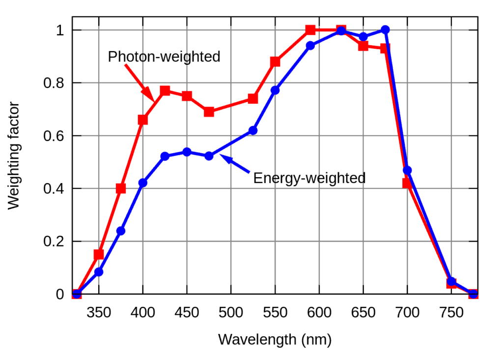
Here the horizontal axis shows the wavelengths of radiation, while the vertical axis shows the weighting coefficients of photosynthesis efficiency for different wavelengths of radiation. As we can see in this diagram, plants can consume light at wavelengths from approximately 350 nm to 750 nm for photosynthesis processes. However, the light absorption efficiency at wavelengths between around 400 and 700 nm does not differ fundamentally. For example, the photosynthesis efficiency for wavelengths of 550 nm and 415 nm differ only about one-third.
Now let’s see what the radiation visibility diagram for the human eye looks like [8]:

Here the horizontal axis shows the wavelengths of radiation, and the vertical axis shows the visibility of this radiation by the human eye. For example, if we take the radiation visibility at a wavelength of 555 nm for 100%, then the violet light with a wavelength of 415 nm has only 1% visibility. That is, the human eye sees this radiation as 100 times less bright!
Thus, any part of the visible spectrum is almost equally useful for plants, while the human eye sees only the yellow-green region of the spectrum well. Simply put, there is practically no radiation that the human eye can see, that plants could not use for their nutrition! That is, any lamp that emits light visible to the human eye would be suitable for lighting aquarium photosynthetics. Only one thing is required – to give enough radiation for this photosynthetic [9].
This fact 140 years ago was remarkably shown by N. F. Zolotnitsky [1], who achieved in winter, with a lack of natural light, flowering of such a pretty whimsical plant as Uvirandra (Aponogeton madagascariensis):
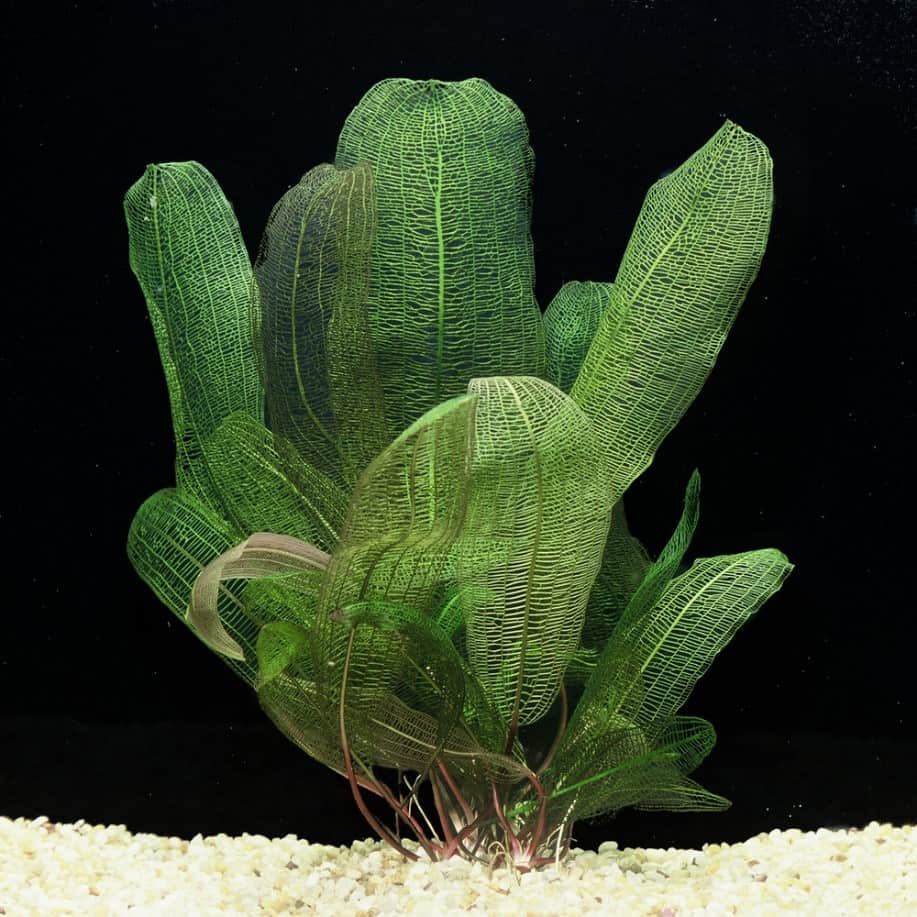
To provide this plant with light, he used the light of a kerosene lamp!
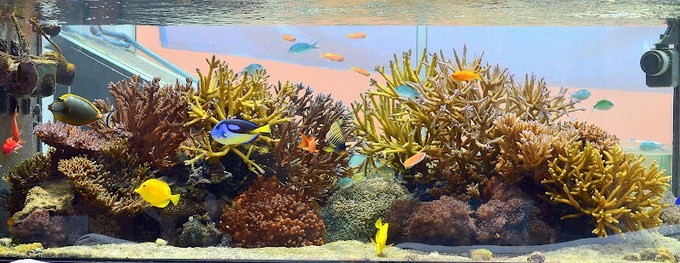
Separately, we will briefly focus on marine photosynthetics, in particular, corals, which adapted to the spectrum of the sun, which changes markedly depending on the depth [8]:

This fact seems to impose strict limits on the spectrum that we should use to light corals, doesn’t it? But practice shows that not only freshwater plants but also corals grow successfully under the typical solar spectrum. For example, not so long ago, so-called “solar tubes” were used to illuminate aquariums, including those with corals, which deliver sunlight directly into the aquarium’s interior. And this option provides good coral growth. Look at the vast and healthy colonies of corals grown exclusively with this lighting [10]:
Of course, the appearance and color of most aquarium photosynthetics, especially corals, largely depend on the spectrum used. We will dwell on this in more detail below.
If aquarium photosynthetics can be successfully grown under any luminaire with sufficient radiation, what do we get with special luminaires specifically designed for an aquarium? The answer to this question was also given in the mentioned book by Zolotnitsky [1], where he wrote about the use of light filters in luminaries:
“.. different glass colors are inserted into them so that the water kingdom can be illuminated, if desired, either red, green or blue, etc.
Lighting is, in addition to decorating the underwater landscape … also important as a means of showing the bright colors of the fish.”
That is, the luminaires with a controlled spectrum allow you best to emphasize the beauty of the aquarium’s inhabitants. And since personal spectral preferences are unique for each person, the luminaires’ whole beauty with a controlled spectrum is that they allow you to pick up just the spectrum that a particular person likes.
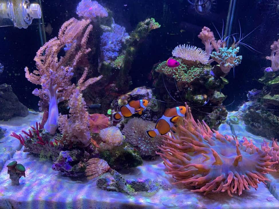
Look at how the same aquarium [10] looks like under another light spectrum:

Probably many of you like the second photo of this aquarium better, don’t you?
In the case of controlled-spectrum luminaires, you can find almost an infinite number of spectra that will look very different to the human eye, and for corals, they will be nearly the same. This is due to the sharply pronounced sensitivity of the human eye to different parts of the spectrum, as shown above in Fig.7.
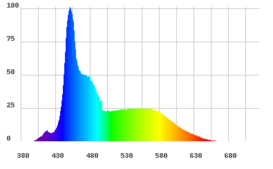
For example, let’s consider two typical “marine” spectra, i.e., those that are often installed by aquarists for their marine aquariums. The first spectrum looks like this:

The second spectrum looks like this:

Both of these spectra can contain the same amount of radiation in the region of 400-500nm. Therefore, they will differ minimally in their effects on corals [8], but they will look entirely different to the human eye! Look at how these same spectra will look, considering the visibility of radiation to the human eye. The first spectrum will look like this:
And the second one is like this:
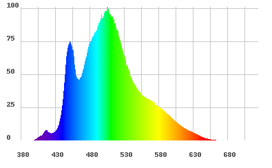
By the way, the second spectrum, with a relatively large number of turquoise parts, looks attractive to many aquarists. It imitates well the natural turquoise color of the water in the lagoon coral reef. Of course, personally, you may prefer any of these spectra. You can use any of these spectra for your aquarium as you like. The corals will like both in precisely the same way.
Because much of the corals’ beauty is due to their fluorescence, you will automatically want to use a significant amount of short-wave spectrum radiation. That is, you will automatically select those spectra that will allow corals to color themselves in the best possible way [8].
Although corals can adapt to almost any radiation in the PAR region, their habitus and coloration depend largely on the spectrum [8]. Even a small amount of radiation with wavelengths greater than ~550 nm can lead, due to the phenomenon of chromatic adaptation, to the formation of light-gathering pigments with brownish, not bright colors.
In the case of freshwater aquariums, spectrum building nuances are much greater than in marine aquariums. The vast majority of plants that are kept in freshwater aquariums live in nature at a very shallow depth, so they can successfully utilize a much wider part of the spectrum. Unfortunately, consideration of all these nuances is beyond this article’s scope, but in general, we can say that for the successful growth and good coloring of freshwater plants, they need to form spectra that are not fundamentally different from the solar, shown in Fig. 5.
There is one subtle but not insignificant point that we would like to make. It is believed that only three color channels R, G, B are enough to create a color sense of any color. Right now, you are most likely looking at the screen that forms the image by these three channels. However, the color palette that can be generated by these three channels is not ideal, but only acceptable, as it is impossible to reproduce several colors with these three channels, such as pure blue and orange. This method of color formation is also a large disadvantage for aquarium applications due to the lack of color channels. It manifests itself that when one channel increases brightness, other channels decrease it [11]. Also, about 20% of the brightest so-called extraspectral colors cannot be reproduced in such a color model at all.
Take a look at the color wheel –

The colors above indicated by black stripes, are the ones you cannot see now. Your display device only has a rough imitation of them.
Also important is the fact that when we look at the aquarium, we don’t look at the light from the lamp, but the light reflected from objects inside the aquarium. Therefore, if there is no part of the light in the luminaire spectrum and it doesn’t appear due to the fluorescence in the aquarium, we won’t be able to see it. In other words, the color palette of the aquarium will be incomplete.
Obviously, the RGB model’s drawbacks result from insufficient coverage of the spectrum visible to the human eye. In the diagram below, we can see which spectrum of illumination should be simulated by a luminaire with a controlled spectrum:

Here the gray color shows the part of the solar spectrum visible to the human eye. Blue shows how this spectrum can be simulated with a three-channel RGB luminaire. The orange shows how this spectrum can be simulated with a 16-channel LED luminaire. As it is easy to see, three-channel RGB luminaires are entirely unsuitable for this task.
Fortunately, aquarists don’t need to emulate the entire solar spectrum shown in Fig. 5. The matter is that under water, there are no spectra with a high fraction of radiation with wavelengths more than 700 nm, which plays a vital trigger role for terrestrial plants [12]. Therefore, it is enough to emulate part of the spectrum from about 360 to 700 nm. As practice shows, such a task can be solved with a set of 7-8 types of LEDs with different wavelengths. If a set of LEDs contains 12 varieties, this task is solved almost perfectly. Of course, in both cases, each type of LED should have its own control channel; otherwise, it is difficult to talk about the possibility of spectrum control in principle.
In general, the strategy to build a light in any aquarium fits in two simple steps.
- The owner of the aquarium finds the spectra he likes and stores them in the spectra gallery.
- The selected spectra are used to build the daily cycle of lighting. It is only necessary to make sure that the daily amount of radiation corresponds to the required one.
For the luminaire to be able to use this simplest strategy, it must meet several requirements. If not, the desired result will not be obtained, and a successful, beautiful aquarium will not be a regularity but an accident.
Of course, as we have shown above, photosynthetics will grow under any lamp, even the “wrong” one, but we want our aquarium to look the best to us visually , that’s why we created it, isn’t it?
First of all, let’s look at what we need for the luminaire to form a particular spectrum in principle.
2. The compactness and identity of LED assemblies:
The principal possibility of forming the necessary spectrum
Aquarists are familiar with such a phenomenon as “disco”. It is formed when an aquarium is illuminated by several light sources with different spectra, resulting in its unevenness. It can often even be seen by the human eye in the form of colorful spots on the objects being illuminated.
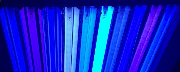
This “disco” can also be the case with conventional fluorescent tube light sources if the luminaire uses tubes with different spectra. The luminaire itself looks like this:
The same problem can occur when LEDs of different parts of the spectrum are spaced a considerable distance from each other in a luminaire:

Even if the LEDs are placed relatively compact:

The result may look truly impressive:
Such a noticeable “disco” is much less striking if there is no wave of water on the surface of the aquarium. Of course, even in this case, the problem shown does not go away – corals do not get the spectrum that the owner of the luminaire would like to provide them.
It is important to note that as we have low visibility of most of the radiation in the PAR area, the full “disco” effect is not visible to the human eye and there insignificantly more unevenness of the spectrum. Because of this “disco” we cannot say that the luminaire can form a spectrum, let alone a spectrum that we need. This may be one of the reasons why corals can be negatively affected by LEDs.
The best solution– to this problem is to have all light sources provide identical and target, precisely what the luminaire owner needs, the spectrum. Since we want the luminaire to have a controlled spectrum, all light sources must contain the LEDs of all parts of the spectrum that are presented in this luminaire. In order to minimize the unevenness of the spectrum, the LEDs should be placed as close to each other as possible.
Thus we get an elementary light source in the form of a LED assembly with tightly mounted LEDs of all parts of the spectrum presented in this luminaire. The LED assembly can look, for example, as follows:
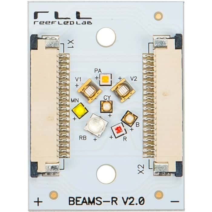
A more powerful version of a LED assembly can look like this:

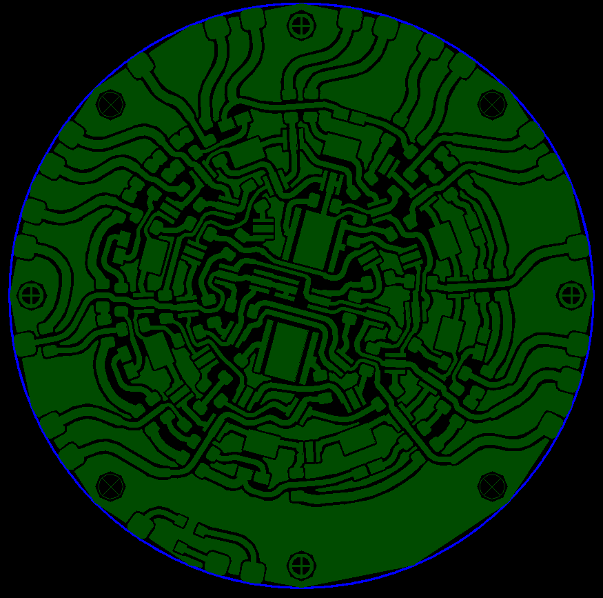
During the construction of such an assembly, many engineering tasks were solved, including a rather complicated board trace, which indicates that our engineers have a “sisu” [13]:
In summary, the LED assemblies should be compact and identical.
3. Uneven location of light sources:
The importance of providing uniform illumination
As we mentioned above, photosynthetics in an aquarium need to provide a certain light level, depending on its appearance. Since many spectra that aquarium owners like, especially marine ones, have low visibility to the human eye, it can be very difficult to determine the light level at a certain point of the aquarium to the eye. It is therefore essential to provide uniform illumination, with predictable intensity, without excessive light points. Such “hot spots” where a photosynthetic receives more light than it needs are fraught with serious problems, ranging from a high sensitivity of photosynthetic to power and water quality, to a high probability of algal growth.
In the practice of aquarium lighting, it is believed that the most uniform lighting creates linear light sources, i.e., fluorescent tubes. However, since the radiation density at any point of such a tube is the same, the closer to the middle of the tube, the more radiation from neighboring areas is added. As a result, the illumination under the middle of the tube can be up to two times greater than at its edges.

When we talk about the lighting of the aquarium surface, i.e., the plane, we often use luminaires with several fluorescent tubes, the number of which is ten or even more. In this case, the hot spot will be located under the geometric center of such a luminaire, and it will be very bright because it will add up the radiation not only from the length of the tubes but also from the width of the luminaire, in which the tubes, as is clearly visible in Fig. 18, are placed evenly.
Let’s see how “hot” can be the point under the center of such a luminaire.
BRS makes a lot of exciting videos where it highlights different aspects of aquaristics. In this video, one of the best fluorescent luminaires was considered. This is the kind of uniformity of illumination it provides:
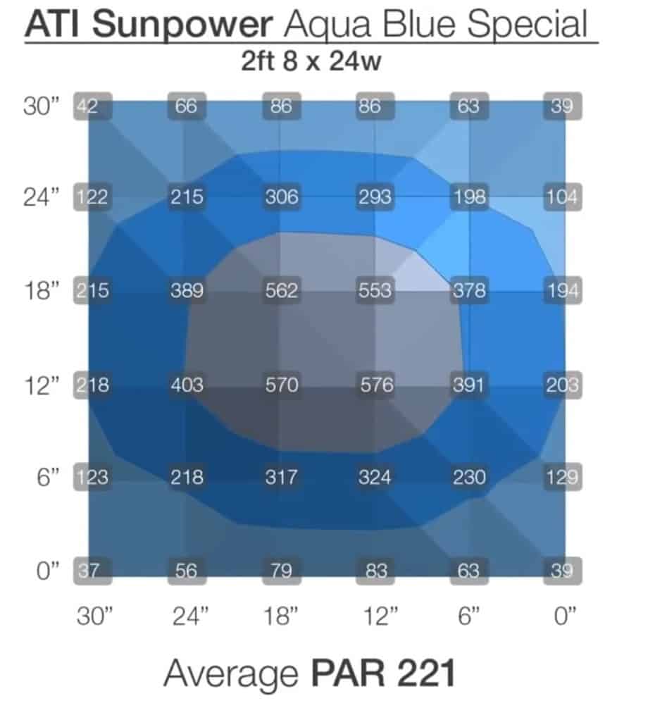
Even in the relatively evenly lit central part of the aquarium, the illumination gradient is about three times, and around the aquarium’s edges – only about ten times! This is what often causes problems with the content of whimsical corals. It’s difficult for the aquarist to position them properly concerning their lighting requirements.
When it comes to illuminating the aquarium with LED luminaires, the illumination gradient is often even more significant because most of these luminaires are in fact, point light sources because the area of the light-emitting part of the luminaire is only a few percent of the area it illuminates.
Only the colossal adaptability of photosynthetics helps them to survive in conditions with significantly different levels of illumination. Look at the data from the average daily measurements of the illuminance in nature for different plant species [14]:

Here LSP (Light Saturation Point) is the saturation point of photosynthesis – the level of light intensity above which further increase in the amount of radiation does not lead to increased photosynthesis rates, which is the limit for this type of plant. LCP (Light Compensation Point) is the minimum light required for a plant when the growth rate starts to exceed the cell death rate. The middle column shows the average light that seems to be close to this species’ optimum light.
Note how low the minimum illumination is for light-loving plants such as Myriophyllum, Bacopa, Nomaphila, Rotala. The range of illumination from minimum to maximum for most photosynthetics is huge and often is five and sometimes ten times. That is, we can put almost any photosynthetic in nearly any place in the aquarium, lit by a conventional fluorescent lamp, and it will most likely receive enough light for at least its existence.
For marine photosynthetics, the range of acceptable light intensity is often even wider. Let’s consider the algae widely used in marine aquariums for exporting nitrates and phosphates: Chaetomorpha linum at 21C (69.8F). Here are numbers found in John Kirk’s 2000 Light and Photosynthesis in Aquatic Ecosystems: Compensation Point: 10 PAR. Saturation Point: 418 PAR.
But if we want to make our photosynthetics have healthy growth and good coloration, we must give them exactly the amount of radiation that will be optimal for them. This is only possible if the luminaire provides a uniform and known density of light flux.
The only way to solve the problem of obtaining a uniform illumination, is to position theLED assemblies in the luminaire at a distance from each other so that their radiation is distributed over the illuminated area evenly. The principle of this arrangement of LED assemblies, is illustrated by this scheme:

Simply put, the LED assemblies in the luminaires must be arranged unevenly to obtain uniform illumination. In general – the closer to the center of the luminaire, the greater should be the distance between the LED assemblies.
As natural measurements show, even in the case of relatively powerful LED assemblies, shown in Fig. 22, the unevenness of illumination (about 20%) can be achieved at a distance of 15 cm from the luminaire. Also, in the case of multiple luminaires for aquarium lighting, we can place them at a smaller distance from each other on its sides and at a greater distance in the center. Thus, the lighting gradient in the aquarium as a whole can be reduced from “traditional” 10 times to about 2-3 times.
So, – true uniform illumination avoided the hot spots and provided simple placement of corals and their healthy growth.
4. Hybrid dimming technology:
Ensuring the accurate installation of spectrum and brightness
To adjust the brightness and spectrum, most aquarium LED lights use pulse-width modulation (PWM). The point is that to adjust the amount of radiation from the LED, short flashes of different duration are formed, which occur at a very high frequency, and is perceived by the human eye as one continuous light of a certain brightness. This control option has become widespread due to its extreme simplicity. However, in fact, PWM interferes with the spectrum of the luminaire and does not provide the necessary brightness. Let us see why this is the case.
For example, let’s take a luminaire consisting of 7 types of LEDs, each with its own radiation spectrum. Let us consider the instantaneous spectrum of the luminaire when the brightness of all channels of LEDs is set with PWM:

In this picture, the height of the bar indicates the duration of the PWM cycle of this LED.
Look at time 1, which is shown with a horizontal line. In this case, all types of LEDs participate in the formation of the luminaire spectrum. At time 2, six types of LEDs are already involved in the formation of the luminaire spectrum. At time 3 – four types of LEDs and at time 4 – only one type!
It may seem that at the moment of time 1 you get precisely the spectrum that is necessary, but in fact, it is not. At this moment, all seven types of LEDs are working at full power. At the same time, they should be working with the current as indicated under the columns that denote every kind of LED. That is, at time 1, all channels of LEDs work at 100% power, while to form the spectrum shown in Fig. 29, they must have power, respectively: purple 81%, blue 99%, blue 63%, and so on.
Therefore, we come to a logical conclusion – a PWM-controlled luminaire never gives the spectrum that the user needs, except for when all types of LEDs work at 100%.
Now let’s take a look at how a PWM controlled luminaire controls the brightness of the luminaire.

The shaded areas in the figure show the time when the current is applied to the LED. We see three special cases of brightness setting – 25 % when the current goes through the LED 25 % of the time and 75 % of the time does not go, 50 % of the brightness when the time of current supply and its absence are the same, and when the brightness is 75 %, in this case the current is supplied to the LED 75 % of the time.
At the same time, when the current is applied to the LED, it produces maximum power.. In other words, the LED gives the maximum possible amount of radiation. In fact, this means that the coral gets short and very bright flashes, interleaved with a complete absence of light. So there is a paradoxical situation – a person assumes that the coral is being illuminated with optimal brightness, but in fact, the coral gets bright, short-term flashes that it cannot fully assimilate because their brightness exceeds its LSP. In other words, a person thinks that the coral is getting enough light, but in fact, the coral is suffering from too much light in short moments on the one hand, and the other hand, from a lack of light on the whole!
The low repetition rate of these flashes causes a flicker that is noticeable to the eye. This leads to rapid eye fatigue, and many people even see this flicker, which is very unpleasant. Unfortunately, the problems with PWM are not limited to negative feelings alone. The flickering of LEDs when using PWM also leads to stripes on video. Of course, starting from the PWM frequency of about 1000 Hz, these effects are practically absent. Even so, however, two critical problems remain unresolved::
- The higher the PWM frequency, the fewer steps to adjust the current level. In PWM with a very high frequency, there may be only a few dozen such steps. This eliminates the possibility of a smooth change in luminaire brightness.
- PWM with a frequency below 2.5 kHz, which is typical for the vast majority of luminaires on the market, reduces photosynthesis efficiency. Scientific works show that this reduction can even be twofold [15]!
Fortunately, there is a technology called Hybrid dimming, which almost eliminates the shortcomings of PWM. The essence of this technology is shown in the following diagram:

In this case, the LEDs in most modes of operation are supplied with a current, the strength of which is adjusted within a wide range of so-called Constant Current Reduction (CCR) method, that is, without the help of PWM. For example, if the driver’s maximum current is 2000 mA and you set the brightness in the control program to 80 %, then the current in the chain of LEDs will go to exactly 1600 mA. If you set the brightness to 20 %, then the current of 400 mA will go into the chain of LEDs, and so on.
Hybrid dimming regulates the current by CCR from the maximum to the minimum recommended by the LED manufacturer in their technical documentation. When it is necessary to obtain very low brightness, then PWM with high frequency is used. The point is that in the case of a low current supply to the LED, there is a significant change in its spectrum. For example, the emission of blue LEDs at low current begins to shift to the long-wavelength range. Their radiation starts to look white at first:
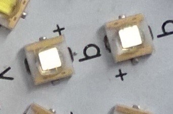
With the further reduction of the current level, their radiation starts to look yellow:

And at an extremely tiny current, even reddish:

To avoid such changes in the spectrum of LEDs, their manufacturers regulate the minimum allowable current.
Also, Hybrid dimming allows you to achieve the maximum possible efficiency for this LED conversion of electrical energy into light.
As we mentioned above, when using PWM, the LED is powered, it gets the maximum current. Therefore, the efficiency of the LED is the same as on this maximum current. At the same time, the efficiency of the LED increases significantly when the current passing through it decreases. Here is a graph of this dependence for a modern white LED:

This graph shows the efficiency of converting electrical energy into light. For the maximum current, it is 0.9, and for the half current, it is 1.08. Therefore for the current, 50 % of the maximum, the efficiency gain in brightness control by CCR relative to PWM is: (1,08-0,9)/0,9*100=20 %.
In controlling the brightness of the LED by PWM, the LED will receive a current of the maximum strength of 50% of its operating time. Thus, the real gain in efficiency for CCR compared to PWM will be half of 20%, that is 10%.
For other types of LEDs, the increase in efficiency compared to PWM with the same average current can be between 5% and 20%, depending on the type of LED. Therefore, adjusting the amount of radiation with CCR saves approximately 10-15% of energy in real-life luminaire scenarios. Note that the saved energy will not heat either the LED crystal or the luminaire heatsink.
We would also like to mention one more important advantage of Hybrid dimming over PWM. The fact that the lifetime of LEDs depends on the current and temperature of the LED crystal. Dependence of lifetime on the magnitude of the current is nonlinear: twice as high a current leads to a reduction in the LED’s life not in 2 times, but 3-4.
If it does not exceed the manufacturer’s limits, the effect of increased temperature for modern LEDs is not as strong as for the first generations. Therefore, we can sum up that Hybrid dimming for many scenarios of using LEDs can extend their life span by about two times.
So, – hybrid dimming provides the true spectra, and the brightness and noticeably increases the efficiency of LEDs and their lifetime.
5. Maximum decorative effect by using diffuse light:
Providing a homogeneous spectrum of the luminaire and light to the lower parts of the corals
N.F. Zolotnitsky in his book [1] noted:
“diffused light … has a wonderfully beneficial effect on the development of vegetation in the aquarium, on its abundant oxygen release and at the same time … slows down the growth of algae.
[plants] should not be planted too tightly, but so that there is free space between each of the plants and that light can illuminate them from top to bottom. Especially, make sure that their lower parts are illuminated.”
His opinion about the benefits of diffused light has been confirmed by modern research [16]. Aquarists also know very well that both corals and plants look the most decorative only if their lower parts receive sufficient light.
Unfortunately, as we mentioned above, many aquaria LED lights are point light sources. That is, the light from them has a narrow pattern of direction, and the aquarium shows sharp light transitions with “hard” shadows, and such light is poorly penetrated to the lower parts of the photosynthetics.
Recently, LED lighting manufacturers have started to use diffusers or use a matte coating on the secondary LED optics’ outer surface. Unfortunately, the first solution is often used without a reflector, leading to significant light loss. The second solution, in principle, can not provide the required effect. The use of mirror reflectors in controlled-spectrum luminaires is, in principle, unacceptable, be it conventional reflectors or TIR lenses [17], because such solutions do not allow obtaining good spectrum uniformity.
Let us see what happens when we try to use a standard mirror reflector. The same effect will be with TIR optics because it also uses a mirror reflection. Let us install a reflector on a very dense LED assembly shown in Fig. 23 and take a picture of the result of this optical system on the screen:
As you can see, the “disco”, reflected from the walls of the reflector, is quite noticeable.
Let’s see now what the same LED assembly looks like with a reflector with a Lambertian, that is, diffuse reflection:

As you can see, the “disco”, reflected from the walls of the reflector, has completely disappeared. If we add a diffuser to the light flux output from the reflector, the “disco” from the LEDs in the central part will also be almost completely eliminated.
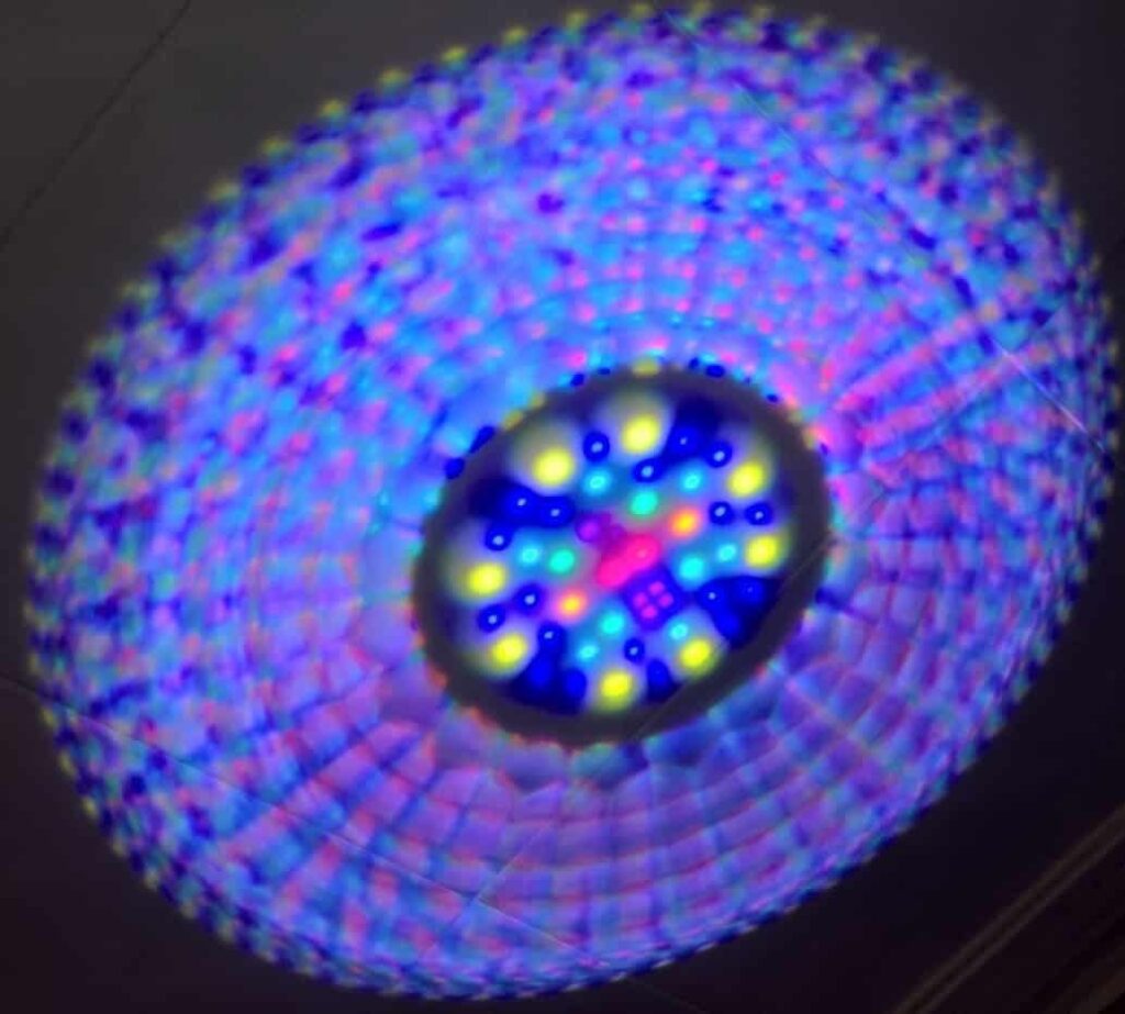
What can be other variants of the solution to this problem? Maybe it will be possible to get rid of the “disco” without the use of reflectors made of unique material if the LEDs are placed extremely tightly, as tightly as possible? We checked this option as well. Together with TSLC, we developed a unique LED. It consisted of 12 types of LEDs with united primary optics, in a 9x9mm case, each LED was controlled separately from the others:
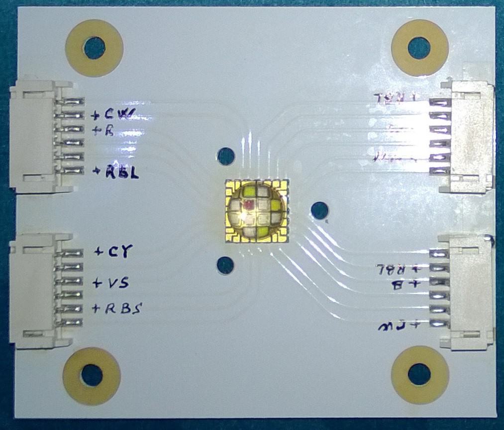
Unfortunately, the “disco” from this LED was quite noticeable because the single primary optics of this LED turns the LED crystals into “flashlights”, which shine in its solid angle.
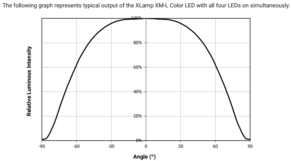
An illustration of this fact can be a diagram of the radiation distribution for such a four-crystal LED TSLC T5050M:

Such diagrams were initially specified in the documentation of all four crystal LEDs with a single primary optics, including LEDs produced by Cree. However, later on, this manufacturer began to indicate not a channel diagram, but a summary diagram of the radiation distribution, which in the documentation for the XLamp® XM-L® Color LED now looks like this.:
Recently, there have been luminaires that have a diffuser but do not have a reflector. In this case, the luminaire may have a slim profile because, in this case, there is no need to place a reflector in it, which works better, the greater its physical size. Unfortunately, in this case, we get a very wide luminous flux from the luminaire. Much of the light passes by the aquarium and often falls into the eyes of the person watching the aquarium. This glare effect is very unpleasant, and the manufacturers have to use relatively large deflectors to combat this effect.
This is what an LED luminaire equipped with a diffuser looks like, but without a reflector, from a brand known for its perfectionism [18]:
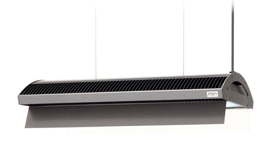
As you can see, the deflectors are so large that they make the luminaire structure extremely cumbersome.
Of course, a reflector with the diffuse reflection of light cannot perfectly shape the luminaire light flux, completely eliminating side lighting. But don’t forget that the complete absence of lateral illumination is impossible to achieve even with luminaires, which essentially point light sources equipped with TIR optics. In particular, to solve this problem in the luminaires of AI Prime HD, third-party manufacturers offer such deflectors [19]:
Our practice shows that intelligently designed reflectors with diffuse reflection already at a relatively modest size quite successfully solve the problem of forming a light flux with negligible lateral illumination.
So, – using the special reflector and diffuser is necessary for an aquarium luminaire.
Let’s summarize:
The luminaire is the most powerful tool for creating the beauty of your aquarium. It is not intended primarily for plants or corals in your aquarium, but for you to visually create an aquarium that you like.
The luminaire, which will successfully solve the tasks of forming the most beautiful appearance of your aquarium and also create the most comfortable conditions for photosynthetics, should have the following engineering solutions:
- Compact and identical LED assemblies containing at least 7 LEDs with different spectra, each with a separate control channel.
- Unevenly arranged LED assemblies for uniform illumination.
- Hybrid dimming brightness control to set true spectrum and true brightness.
- Reflector with diffuse reflection and diffuser.
Such a luminaire will make your hobby much more enjoyable and the aquarium – much more beautiful!
References
- Н. Ф. Золотницкий. Аквариум любителя. 1885.
- https://en.wikipedia.org/wiki/Photosynthetically_active_radiation
- https://www.apogeeinstruments.com/full-spectrum-quantum-sensor/
- https://www.seneye.com/catalog/product/view/id/20/s/seneye-reef/category/5/
- https://en.wikipedia.org/wiki/Color_temperature
- https://en.wikipedia.org/wiki/Color_rendering_index
- https://www.sciencedaily.com/releases/2020/10/201002091027.htm
- https://reefs.com/magazine/light-in-the-reef-aquaria/
- https://onlinelibrary.wiley.com/doi/abs/10.1111/php.12233
- https://forum.zeovit.com/forum/picture-forums/tank-gallery-all-languages/24659-adee-s-sunlit-reef
- https://studbooks.net/2237619/informatika/dostoinstva_ogranicheniya_tsvetovoy_modeli
- HOW LIGHT REGULATES LIFE OF PLANTS N. KULAEVA
- https://www.bbc.com/worklife/article/20180502-sisu-the-finnish-art-of-inner-strength
- “The Complete Book of AquariumPlants”, Robert Allgayer and Jacques Teton (1987, ISBN 0-7063-6614-X)
- https://www.researchgate.net/publication/259202813_Efficiency_of_Photosynthesis_in_Continuous_and_Pulsed_Light_Emitting_Diode_Irradiation
- Advantages of diffuse light for horticultural production and perspectives for further research. Tao Li, Qichang Yang
- https://www.osram.us/ledengin/products/lenses/index.jsp
- https://www.adana.co.jp/en/contents/products/na_lighting/detail05.html#series-box1
- https://www.thingiverse.com/thing:3698357